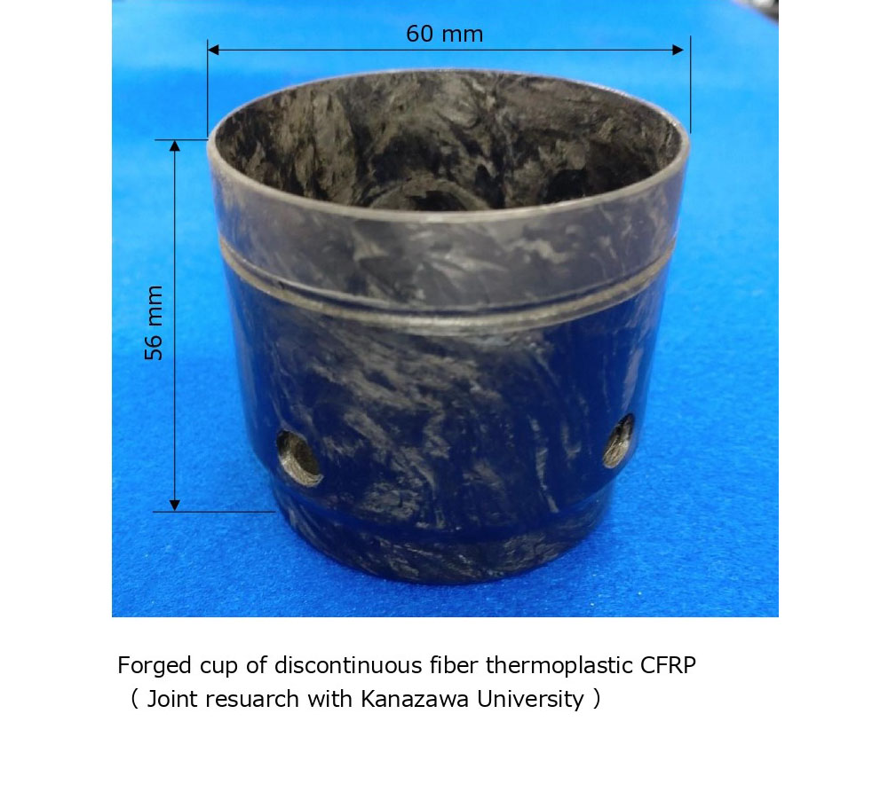
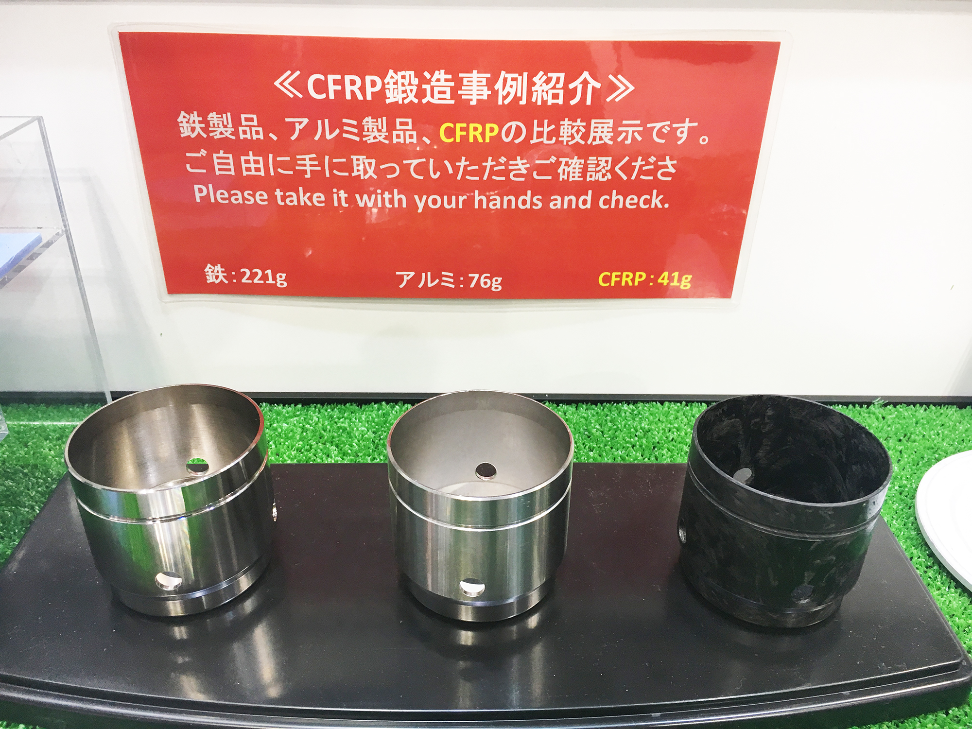
Forging with thermoplastic discontinuous CFRP
1.Introduction
Since carbon fiber reinforced plastic (CFRP) is lightweight and has high strength, thermoplastic CFRP
(hereinafter referred to as CFRTP), is expected to reduce the weight of transportation equipment and
improve fuel efficiency. It can be molded in a short time. Continuous fiber CFRTP is expected to
have high strength, but there are restrictions on the moldable shapes. By using CFRTP, which is a
discontinuous fiber cut into a certain length, although the strength of discontinuous fiber CFRTP is
inferior to continuous fiber, it has the potential to be molded into a variety of shapes.
Therefore in this study, as a discontinuous fiber CFRTP a flat plate obtained by cutting a
unidirectional carbon fiber to a predetermined length and forging of complicated-shaped parts is
performed to elucidate the molding behavior and conditions.
2.Molding target
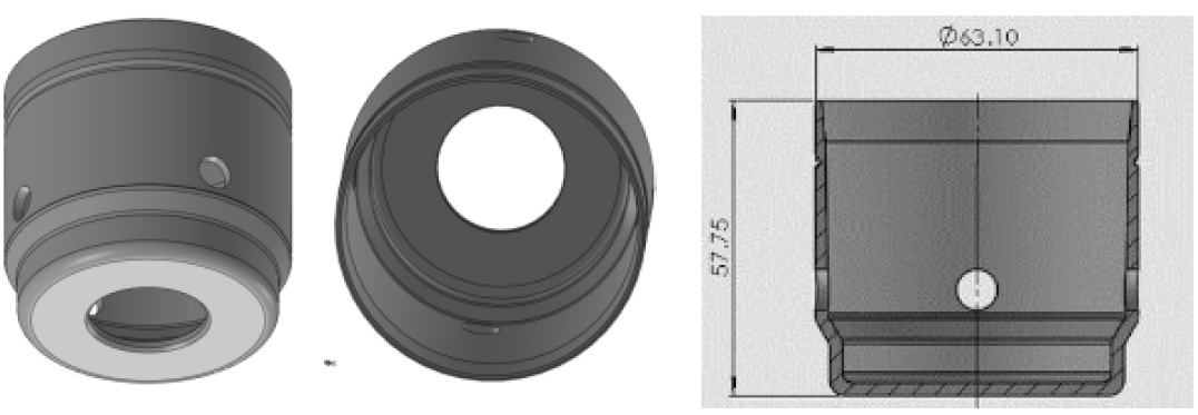
The molding target is a cup-shaped object. Figure 1 shows a 3D model and cross-section view of the model product
3.Experimental equipment and Sample
3.1 Forging die
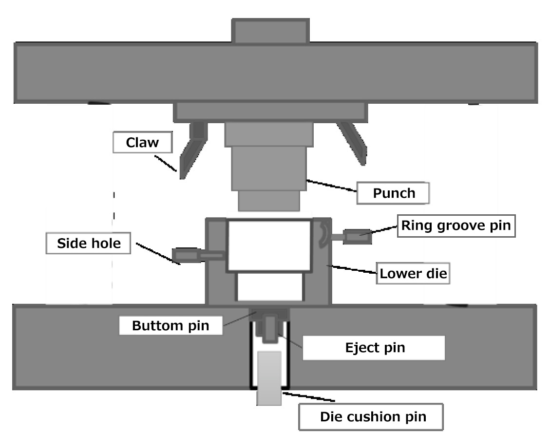
Fig 2 shows the structure of the forging die. A punch is inserted into a lower mold having a cup-shaped cavity. The material is placed on the bottom of lower die, pressed with punch and molded by backward extension. A heater is built in the lower die, punch and the die is heated near the melting temperature of the base resin of CFRTP to mold before it cools to the solidification temperature. After molding the heater turns off and naturally cools to solidify the resin. Since the material shrinks due to heat during the cooling process, we aimed to continue pressurizing the material that had entered the eject pin part of the lower mold with the die cushion pin. When the claw is inserted the side hole pin and the ring groove pin slide inwards for molding.
3.2 Forging material
As a forging material, a UD sheet of CFRTP infiltrated with nylon PA6 is used.
The thickness of UD sheet is 0.16mm and VF is 50% and fiber length is 30mm.
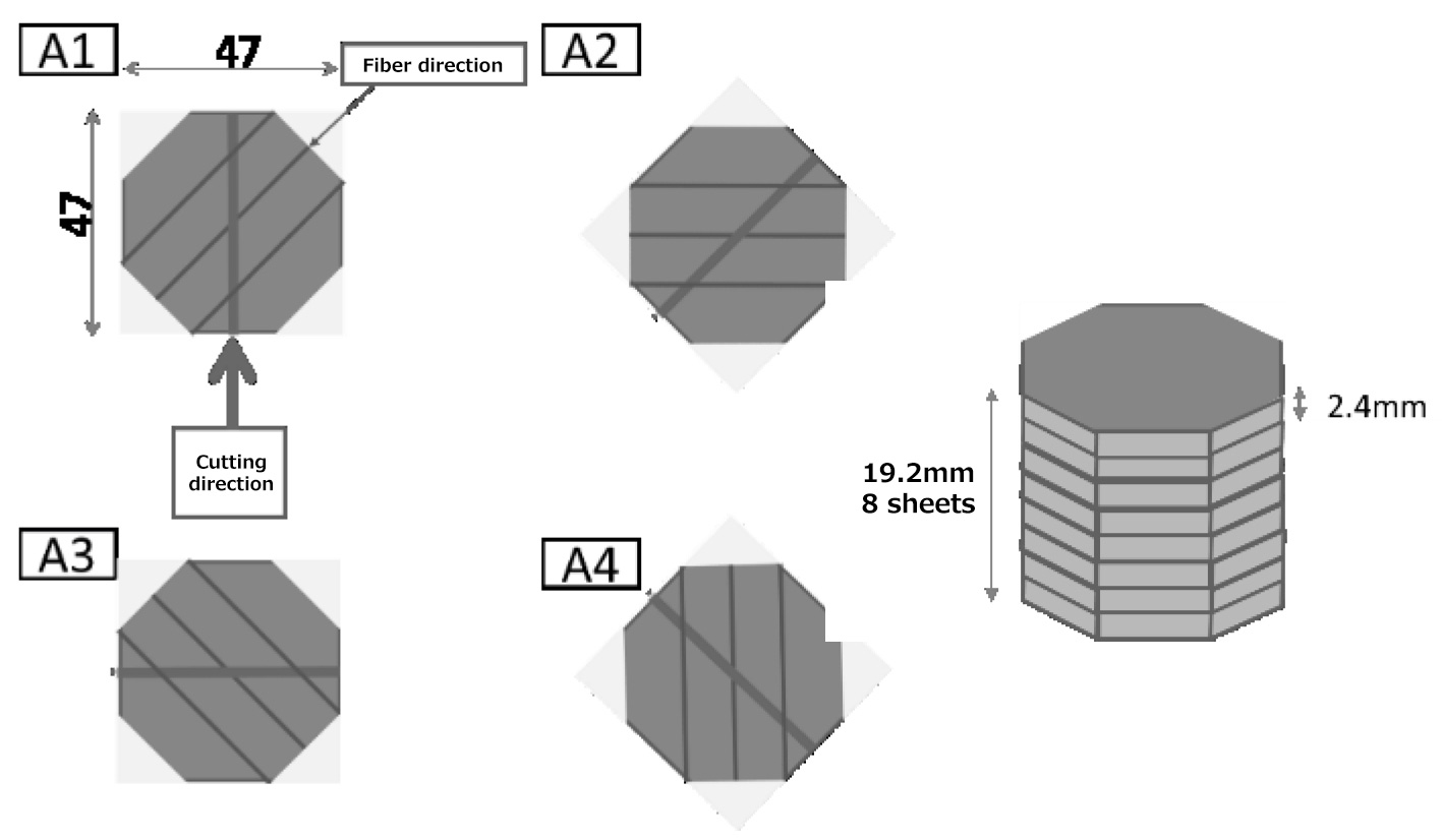
The cut direction was 45° with respect to the fiber.
UD cut sheets are stacked in difference of 45°.
The molding process of the UD cut sheet to laminated plates are as follows.
(1)Stack 16 UD sheets.
(2)Place the stacked CFRTP sheet on a heated mold and heat to molten state.
(3)Crimp the CFRTP sheets.
(4)Take out the molded product from the die.
Figure.3 Molded UD cut sheet laminated plate.
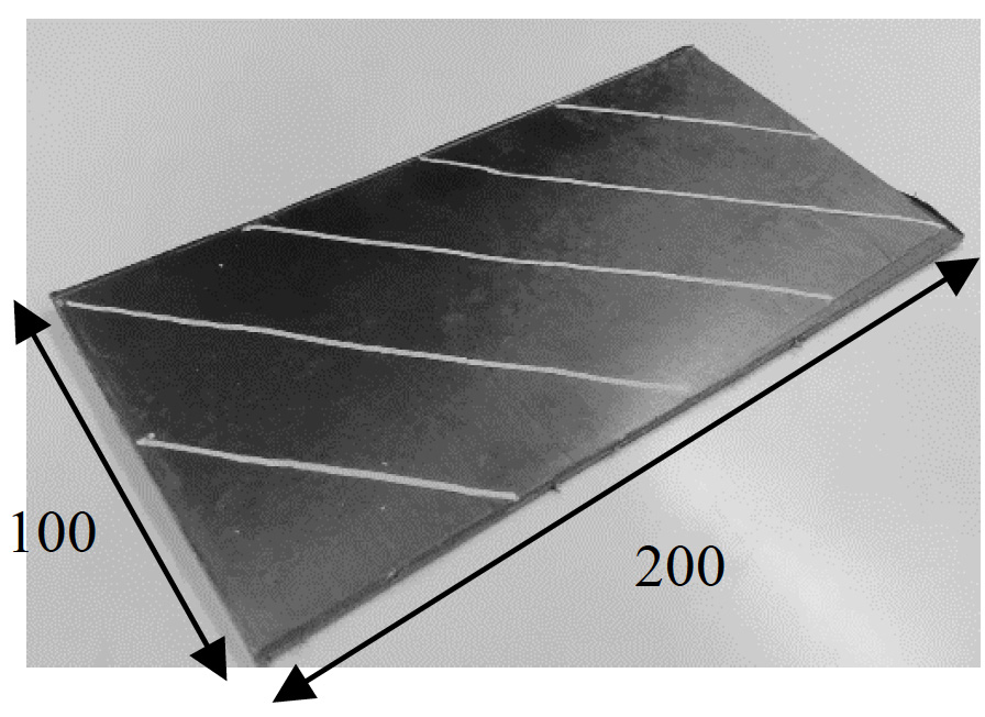
The UD cut sheet laminated board is a stack of 16UD sheets. The fiber direction and the cutting
direction are shown in fig.4.
An octagon was cut out from the UD cut sheet laminated board and eight of these were stacked to make
a material for forging.
3.3 Press machine
We used a hybrid AC servo press H1F45 manufactured by Komatsu industries corp. The stroke is 100mm and the maximum load is 450 KN.
4.Forging conditions
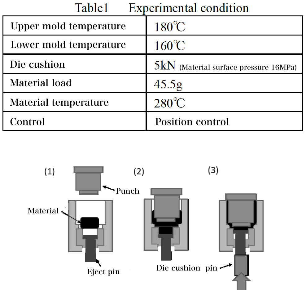
Table.1 shows the forging conditions. The molding process is shown in fig.5
(1)The material is heated to 280ºC inside a 300ºC muffle furnace and inserted into the lower
mold.
(2)Lower the punch position control. The punch comes in contact with the material and causes the
material flow.
(3)Push the die cushion with air pressure and slide the eject pin. There is a time lag until the air
pressure reaches the set pressure. Natural cooling and heat shrinkage of the material makes the
eject pin slide further.
5.Experimental results
5.1 Molded product appearance
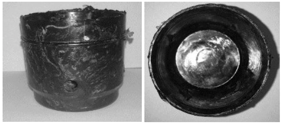
Molded product appearance is shown in fig.6.The upper part of the molding is filled. At the top part of the side hole, material confluence can be seen. The model product is a distorted circle with a maximum outer diameter of 63.2mm and a minimum diameter of 62.4mm with respect to the design dimension of 63.1mm.
5.2 Molding load
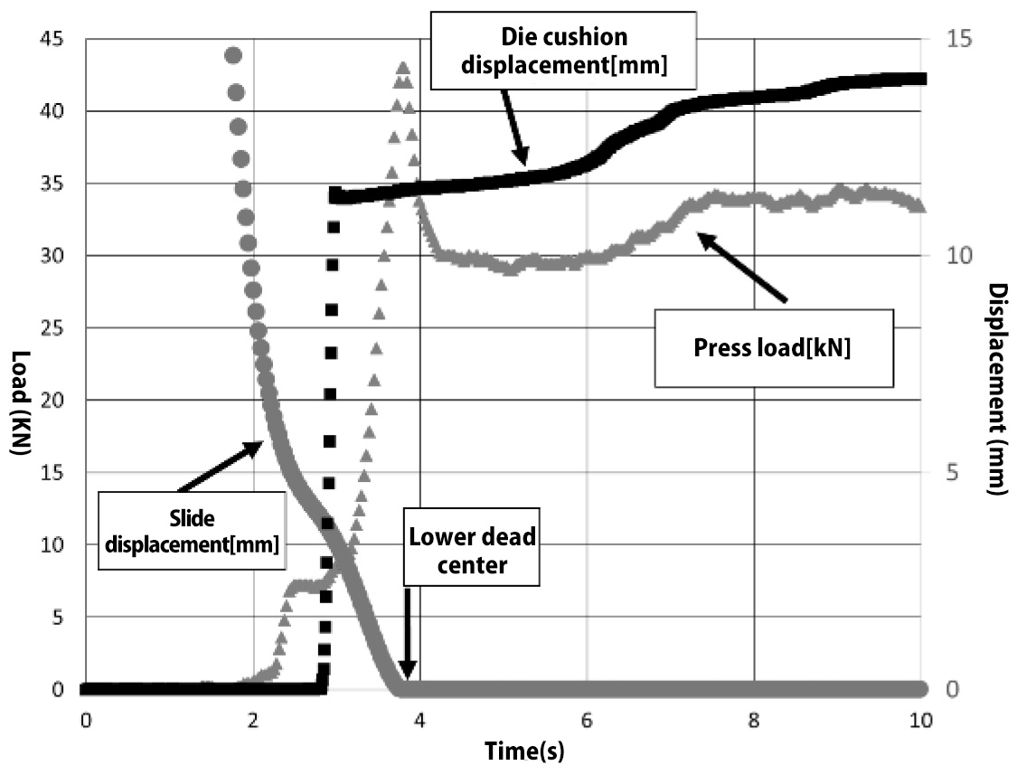
The time waveform of press load during molding, slide displacement, die cushion displacement is shown in fig.7. Slide displacement 0mm represents the lower dead center. When the slide position is 10mm the punch comes in contact with the material the load increases causing the material to flow. When the lower dead center is reached, the maximum load becomes 43KN and the material surface pressure is 14MPa. After exceeding the load peak, it again rises up to 35KN. After that, the load gradually decreases. The die cushion is 11.5mm and after contraction of the eject pin once, the die cushion load rises up to 5KN and during the process, it increases up to 14mm. After 6s, it increases to 15mm.It can be considered due to heat shrinkage of the material.
6.Cross-section observatio
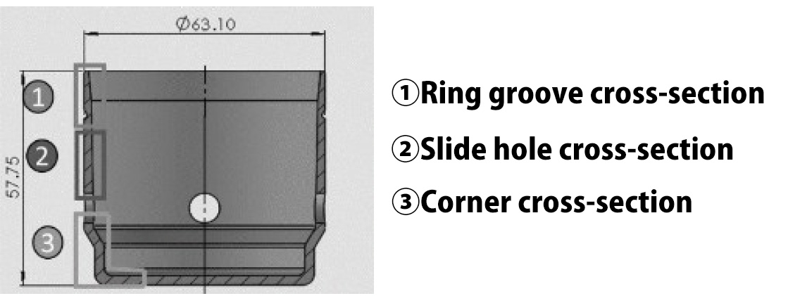
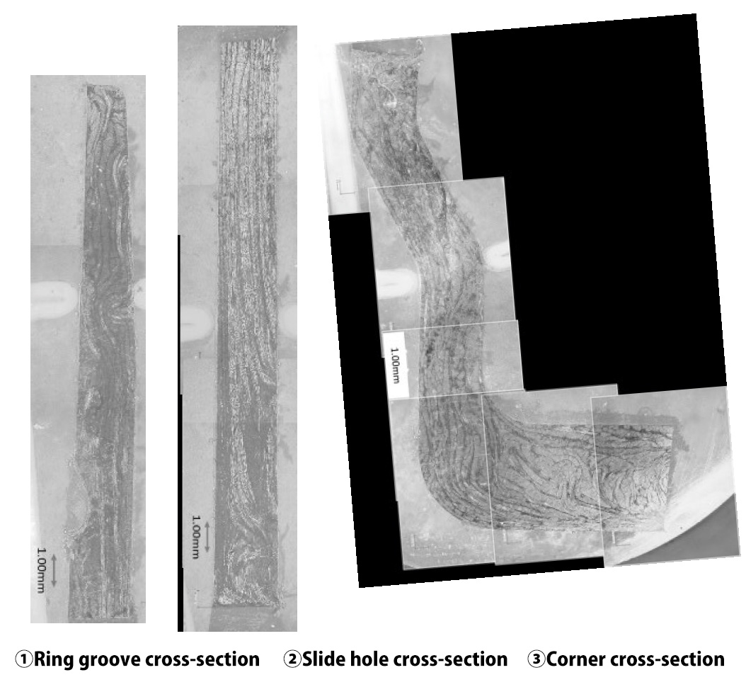
With an optical microscope, the ring groove cross-section, side hole upper cross-section, and corner
cross-section of the side hole of the model product were observed. The cross-section observation
position is shown in fig.8. The cross-section photograph is shown in fig.9.
Bent flow can be seen in the upper part of the ring groove. Even after the material reaches the top
it is possible that it continued to be pushed. It can be confirmed that the layer of carbon fiber
perpendicular and parallel to the cross-section is laminated on the upper part of the horizontal
hole. Bent flow can be seen in one part of the corner.
7.Conclusion
Using a flat plate obtained by cutting CFRTP unidirectional carbon fiber to a predetermined length
and stacking them by changing the fiber direction, forging of complex shapes could be performed.
The material flow and lamination inside the molded product were confirmed by cross-sectional
observation using an optical microscope. Strength tests will be conducted in the future. This
research was supported by the Amada Foundation.
